A Cube Is an Example of a? Art 1
Contents
- 1 Introduction
- 2 Creating our first model and the interface
- 2.1 First model
- ii.ii The software - compiling scad code
- 3 Some 3D principles
- 4 Example code
- four.1 Using existing models
- 4.2 Elementary door stopper
- 4.3 Door stopper
- four.iv Parametric Lego Duplo block
- v The OpenScad language
- 5.one Modules
- 5.2 Control flow
- v.ii.1 For Loop
- 5.2.2 Intersection For Loop
- 5.2.three If Statement
- 5.3 Variables and assign Statement
- 5.four Mathematical operators and functions
- v.5 Functions
- 5.6 Special variables
- 6 Primitive Solids
- 6.1 Cube
- 6.ii Sphere
- half-dozen.iii Cylinder
- six.4 Polyhedrons
- vii Transformations
- vii.1 scale
- 7.2 rotate
- 7.three interpret
- seven.four mirror
- 7.five multmatrix
- seven.half-dozen color
- vii.7 minkowski
- 7.viii hull
- viii CSG Modelling
- 8.one Principle
- 8.2 Merging of objects
- eight.three Difference
- 8.4 Intersection
- viii.5 Modifier characters - aid for composing
- eight.vi Unproblematic CSG examples
- 9 second geometry and linear extrusion
- ix.ane Polygons
- 9.2 Linear 2D to 3D extrusion from builtin 2D shapes
- ix.three Import and extrude 2D graphics from SVG
- ix.iii.1 Legacy procedure - Transforming and SVG file to a usable DXF file with Inkscape
- nine.4 Creating 3D text
- 9.5 2D DXF drawings extracted from 3D STL shapes
- 10 Troubleshooting
- ten.1 Tracing
- 10.2 Not simple objects
- 11 Thingiverse Customizer
- 12 Links
- 12.1 Tutorials
- 12.2 In education
- 12.3 Thingiverse Customizer
- 12.4 Geometric forms / 3D models
- 12.5 Software
- 12.vi Alternatives to OpenSCAD
- xiii Credits and copyright modification
1 Introduction
"OpenSCAD is a software for creating solid 3D CAD objects. Information technology is free software and available for Linux/UNIX, MS Windows and Apples OS X. Different most complimentary software for creating 3D models (such as the famous application Blender) it does not focus on the artistic aspects of 3D modelling but instead on the CAD aspects. Thus it might be the awarding yous are looking for when you are planning to create 3D models of machine parts simply pretty sure is not what y'all are looking for when you are more interested in creating reckoner-animated movies. OpenSCAD is not an interactive modeller. Instead it is something like a 3D-compiler that reads in a script file that describes the object and renders the 3D model from this script file (see examples below). This gives y'all (the designer) full command over the modelling process and enables you to easily change any step in the modelling process or make designes that are defined by configurable parameters." (http://openscad.org/, retrieved 22:58, 17 March 2010 (UTC)
OpenScad should run on nearly computers. However a good CPU and a good graphics card aid. If OpenScad models are too slow, effort to cut down triangles in circles. In that respect, run into the $fa, $fs and $fn special variables explained below.
See likewise:
- the official OpenSCAD User Transmission !
- Doblo factory, a set of modules for creating duplo-uniform structures, bricks and mashups.
- Tutoriel OpenSCAD (french version)
2 Creating our first model and the interface
This department shorly explains how to use OpenScad and its programming interface.
2.1 First model
For our first model we will create a uncomplicated ii ten three x four cuboid. In the openScad editor type the following one-line command:
cube([ii,3,iv]);
This will define a uncomplicated cube of size x=2, y=3 and z=4.
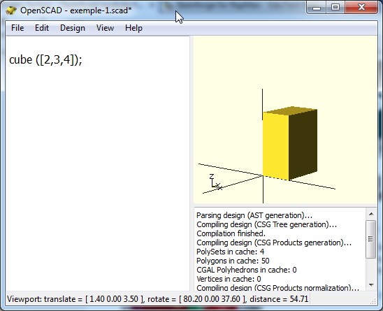
Cube
The cuboid tin can now be compiled and rendered as we shall testify below.
2.2 The software - compiling scad code
The Interface looks like this:
- To the left an editing window. Of course you could use an external editor, e.g. I apply emacs considering it can format (employ c-mode or install an openscad mode)
- To the right the rendering window.

Screenshot of OpenScad 2010.03.08
- To open up a .scad file
- card: File->Open
- To compile (see the consequence)
- menu: Design->Compile or F5
- Use card: Reload and compile or F4. If you prefer using an external editor for editing .scad lawmaking, the program volition observe alter of file appointment and automatically reload. I employ emacs in club to go "real" indentation back up and skilful syntax high-lighting).
- To return for existent and to export
- menu: Design-> Compile and Render (CGAL) or F6 .... this can accept many minutes. However, various parts are cached and the next rendering could exist much faster.
- menu: Blueprint-> Export every bit .STL
- Once you compiled and rendered (CGAL)
- Y'all can view the CGAL grid simply (Bill of fare: View->CGAL Grid Only or F11)
- The View Carte du jour
- Tick "Show Axis"
- You may switch between "Open up CSG" and "Thrown together" fashion for looking at the outcome
- Once an object is rendered (non just compiled), you may explore the other options. In the same menu yous will find various selection to look at compiled or compiled + rendered models. Explore these and remember some shortcuts.
3 Some 3D principles
Information technology's good to understand some of the 3D terminology, in order to be able to follow instruction or to figure out why things went wrong...
"The basic object used in mesh modelling is a vertex, a indicate in three dimensional infinite. Two vertices connected past a directly line become an border. Three vertices, connected to the each other past iii edges, define a triangle, which is the simplest polygon (confront) in Euclidean infinite. More circuitous polygons can be created out of multiple triangles, or as a single object with more than than three vertices. Four sided polygons (generally referred to every bit quads) and triangles are the most common shapes used in polygonal modeling. A group of polygons, connected to each other by shared vertices, is more often than not referred to as an element. Each of the polygons making upward an element is called a face up." (Polygonal modeling, Wikipedia))
"In geometry, a vertex (plural vertices) is a special kind of betoken which describes the corners or intersections of geometric shapes. Vertices are commonly used in computer graphics to define the corners of surfaces (typically triangles) in 3D models, where each such indicate is given as a vector. A vertex of a polygon is the point of intersection of ii edges, a vertex of a polyhedron is the point of intersection of iii or more than edges or face." Vertex geometry, Wikipedia, retrieved 17:25, 23 March 2010 (UTC)
The faces or facets define the surface of a 3-dimensional object, i.e. what is between "outside" and "inside".
"Many modeling programs do not strictly enforce geometric theory; for example, it is possible for two vertices to have 2 distinct edges connecting them, occupying the exact same spatial location. It is too possible for ii vertices to exist at the same spatial coordinates, or 2 faces to be at the same location. Situations such as these are usually not desired and many packages support an auto-cleanup office. If auto-cleanup is not present, however, they must exist deleted manually." Vertex geometry, Wikipedia, retrieved 17:25, 23 March 2010 (UTC)
"A group of polygons which are continued together past shared vertices is referred to as a mesh. In order for a mesh to announced bonny when rendered, it is desirable that it exist non-self-intersecting, meaning that no edge passes through a polygon. Another way of looking at this is that the mesh cannot pierce itself. It is too desirable that the mesh not contain any errors such as doubled vertices, edges, or faces. For some purposes it is important that the mesh be a manifold – that is, that it does not contain holes or singularities (locations where two singled-out sections of the mesh are connected by a single vertex)." Vertex geometry, Wikipedia, retrieved 17:25, 23 March 2010 (UTC)
In many formats, e.k. STL and OpenSCAD, the following principle applies: "(i) The normal and each vertex of every facet are specified past 3 coordinates each, then there is a total of 12 numbers stored for each facet. (two) Each facet is part of the purlieus between the interior and the exterior of the object. The orientation of the facets (which style is ``out and which way is ``in) is specified redundantly in two ways which must exist consistent. First, the direction of the normal is outward. Second, the vertices are listed in counterclockwise club when looking at the object from the outside (correct-paw rule). (iii) Each triangle must share ii vertices with each of its adjacent triangles. This is known as vertex-to-vertex rule. (iv) The object represented must be located in the all-positive octant (all vertex coordinates must be positive)." (Daniel Rypl, Zdenek Bittnar, 2004, retrieved April 2010.
The normal or surface normal is a vector that is perpendicular to a face. Surface normal, Wikipedia, retrieved fifteen:07, xx Nov 2011 (UTC)
4 Example lawmaking
4.1 Using existing models
It is all-time to learn start how to use set up-made OpenScad modules. Download from a identify like thingverse.
Most of these files define modules (aka functions) that you just tin can execute with or without parameters in order to return a model.
Modules without parameters:
The door stopper examples which you can download as thing 2154 from thingiverse are defined as two modules in a unmarried *.scad file, door-stopper-2.scad. Download, or copy/paste the code from hither. Of grade, these door stopper modules really can be parametrized, simply it's done with variables equally you can see.
Modules with parameters:
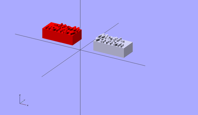
The parametric Lego/Duplo block on the other hand (affair 2014) does include parameters, e.1000. you could call it like this for a pocket-sized 2x2x3 brick with nibbles.
duplo(1,i,iii,truthful);
or like this for a larger brick without nibbles.
duplo(2,2,iv,false);
Just try: compile and change the parameters if they don't suit you. We also created a more sophisticated doblo factory that also may written report.
Modules with named parameters:
You also can use parameter names as opposed to just using positions. The following case would with doblo manufacturing plant.
doblo ( col = 0 , row = iv , up = 0 , width = iv , length = 2 , tiptop = FULL , nibbles_on_off = truthful , diamonds_on_off = false , scale = LUGO ); If default parameters are defined, y'all just could type
doblo ();
in society to become a 4x2 total height typical Lego-compatible brick done.
If you adopt to acquire more about OpenScad before trying, skip these examples and come up back later on.
iv.ii Unproblematic door stopper
The following code will create a doorstopper. Instead of trying to figure out this instance, you as well could skip it and read the rest of this article beginning.
To utilise this module you will have to add the following line to the lawmaking. I.e. it will call the "door_stopper_simple" module:
// To use it, uncomment // door_stopper_simple (); module door_stopper_simple () { top = twenty ; length = 125 ; width = 40 ; half_width = width / two ; borders = 10 ; // ane cm on each side top_cube_length = length - iv * borders ; top_cube_width = width - ii * borders ; top_cube_height = peak ; // get in big plenty top_z = pinnacle / 2 + 4 ; // adjust manually ;) tip_cut_pos = length / 2 - 0.5 ; deviation () { translate ([ - length / 2.0 , 0 , 0 ]) { polyhedron ( points = [[ 0 , - half_width , height ], [ 0 , half_width , acme ], [ 0 , half_width , 0 ], [ 0 , - half_width , 0 ], [ length , - half_width , 0 ], [ length , half_width , 0 ]], triangles = [[ 0 , 3 , 2 ], [ 0 , 2 , 1 ], [ 3 , 0 , 4 ], [ 1 , 2 , 5 ], [ 0 , 5 , four ], [ 0 , i , five ], [ 5 , 2 , 4 ], [ 4 , 2 , 3 ], ]); } // top inset translate ([ - 1 * borders , 0 , top_z ]) { # cube ([ top_cube_length , top_cube_width , top_cube_height ], middle = true ) ; } // cut of the tip a bit interpret ([ tip_cut_pos , 0 , 0 ]) { # cube ([ 20 , width + 1 , tiptop ], heart = truthful ) ; } } } 4.3 Door stopper
The following model is a fleck more sophisticated.
To utilise it: door_stopper ();
// To apply it, uncomment // door_stopper (); module door_stopper () { height = 25 ; length = 120 ; width = 60 ; half_width = width / 2 ; borders = x ; // 1 cm on each side // params for bottom inset bottom_cube_length = length - 4 * borders ; bottom_cube_width = width - ii * borders ; bottom_cube_height = 6.0 ; // 3mm in / 3mm outsite bottom_z = 0 ; // params for top inset top_cube_length = length - four * borders ; top_cube_width = width - ii * borders ; top_cube_height = pinnacle ; // arrive large enough // 25 top_z = pinnacle / 2 + seven.5 ; // 12.v + 7.5 = 10 ; 10 - two.5 = seven.five // param for tip tip_cut_pos = length / 2 - 0.5 ; // param for pinnacle tip top_tip_pos = height + 0.five ; departure () { translate ([ - length / 2.0 , 0 , 0 ]) { polyhedron ( points = [[ 0 , - half_width , meridian ], [ 0 , half_width , height ], [ 0 , half_width , 0 ], [ 0 , - half_width , 0 ], [ length , - half_width , 0 ], [ length , half_width , 0 ]], triangles = [[ 0 , three , 2 ], [ 0 , two , 1 ], [ 3 , 0 , four ], [ i , 2 , five ], [ 0 , 5 , 4 ], [ 0 , 1 , v ], [ 5 , 2 , 4 ], [ 4 , 2 , 3 ], ]); } // lesser inset translate ([ - 1 * borders , 0 , bottom_z ]) { # cube ([ bottom_cube_length , bottom_cube_width , bottom_cube_height ], centre = true ) ; } // top inset translate ([ - 1 * borders , 0 , top_z ]) { # cube ([ top_cube_length , top_cube_width , top_cube_height ], center = true ) ; } // cut of the peak tip a bit translate ([ - length / 2 + 10 , 0 , top_tip_pos ]) { # cube ([ length / 2 , width + two , elevation / 2 ], center = true ) ; } // cut of the front tip a flake translate ([ tip_cut_pos , 0 , 0 ]) { # cube ([ 20 , width + 1 , height ], heart = true ) ; } } } 
You then also could add together some text like this. I did that using netfabb Pro. It allows to create 3D text and to assemble various parts into a single .STL

Door stopper printed with PLA
Below is the printer event.

Door stopper printed with PLA
iv.four Parametric Lego Duplo block
This code is a derivative of the parametric lego duplo. It is the most complicated kind of OpenScad code we played with. Domonoky. We also uploaded it to Thingyverse. People with a expert groundwork in mathematics can get a lot more than out of OpenScad ....
//the duplo itself // parameters are: // width: 1 =standard 4x4 duplo with. // length: 1= standard 4x4 duplo length // height: 1= minimal duplo height // nibbles: true or false duplo ( i , one , 3 , true ); module duplo ( width , length , summit , nibbles ) { //size definitions ns = eight.iv ; //nibble outset offset no = 6.53 ; //nibbleoffset nbo = 16 ; // nibble bottom starting time duplowidth = 31.66 ; duplolength = 31.66 ; duploheight = 9.6 ; duplowall = 1.55 ; //the cube difference () { cube ([ width * duplowidth , length * duplolength , summit * duploheight ], true ); translate ([ 0 , 0 , - duplowall ]) cube ([ width * duplowidth - 2 * duplowall , length * duplolength - two * duplowall , height * duploheight ], truthful ); } //nibbles on summit if ( nibbles ) { for ( j = [ ane : length ]) { for ( i = [ 1 : width ]) { translate ([ i * ns + ( i - 1 ) * no , j * ns + ( j - 1 ) * no , 6.ix + ( tiptop - one ) * duploheight / 2 ]) duplonibble (); translate ([ i *- ns + ( i - 1 ) *- no , j * ns + ( j - 1 ) * no , half dozen.9 + ( peak - 1 ) * duploheight / ii ]) duplonibble (); interpret ([ i * ns + ( i - i ) * no , j *- ns + ( j - ane ) *- no , half-dozen.9 + ( height - 1 ) * duploheight / 2 ]) duplonibble (); translate ([ i *- ns + ( i - one ) *- no , j *- ns + ( j - ane ) *- no , 6.9 + ( height - 1 ) * duploheight / two ]) duplonibble (); } } } //nibble lesser for ( j = [ 1 : length ]) { for ( i = [ i : width ]) { translate ([( i - 1 ) * nbo ,( j - 1 ) * nbo , 0 ]) duplobottomnibble ( height * duploheight ); interpret ([( i - 1 ) *- nbo ,( j - 1 ) *- nbo , 0 ]) duplobottomnibble ( height * duploheight ); interpret ([( i - ane ) *- nbo ,( j - 1 ) * nbo , 0 ]) duplobottomnibble ( height * duploheight ); translate ([( i - 1 ) * nbo ,( j - 1 ) *- nbo , 0 ]) duplobottomnibble ( height * duploheight ); } } //petty walls inside[http://world wide web.thingiverse.com/Domonoky Domonoky] divergence () { union () { for ( j = [ one : length ]) { for ( i = [ 1 : width ]) { interpret ([ 0 , j * ns + ( j - one ) * no , 0 ]) cube ([ width * duplowidth , one.35 , height * duploheight ], true ); translate ([ 0 , j *- ns + ( j - 1 ) *- no , 0 ]) cube ([ width * duplowidth , 1.35 , height * duploheight ], true ); translate ([ i * ns + ( i - 1 ) * no , 0 , 0 ]) cube ([ one.35 , length * duplolength ,, height * duploheight ], true ); translate ([ i *- ns + ( i - 1 ) *- no , 0 , 0 ]) cube ([ 1.35 , length * duplolength , height * duploheight ], truthful ); } } } cube ([ width * duplowidth - 4 * duplowall , length * duplolength - 4 * duplowall , superlative * duploheight + ii ], true ); } } module duplonibble () { difference () { cylinder ( r = 4.seven , h = iv.5 , center = truthful , $fs = 0.01 ); cylinder ( r = 3.4 , h = 5.5 , heart = true , $fs = 0.01 ); } } module duplobottomnibble ( height )[ http : //www.thingiverse.com/Domonoky Domonoky] { divergence () { cylinder ( r = 6.6 , h = top , eye = true , $fs = 0.01 ); cylinder ( r = five.3 , h = peak + 1 , center = true , $fs = 0.01 ); } } 5 The OpenScad linguistic communication
5.i Modules
Modules tin be roughly compared to functions, macros or sub-routines in some other programming language. With modules yous may define reusable code.
Example:
- The module called "thing" is being called from a module called "demo_proj".
source: Example021.scad from the software distribution
module affair () { $fa = thirty ; departure () { sphere ( r = 25 ); cylinder ( h = 62.five , r1 = 12.5 , r2 = 6.25 , heart = true ); rotate ( xc , [ one , 0 , 0 ]) cylinder ( h = 62.five , r1 = 12.5 , r2 = 6.25 , center = true ); rotate ( 90 , [ 0 , i , 0 ]) cylinder ( h = 62.5 , r1 = 12.5 , r2 = half dozen.25 , center = truthful ); } } module demo_proj () { linear_extrude ( center = true , elevation = 0.5 ) projection ( cut = fake ) matter (); affair (); } demo_proj (); - Modules may exist embedded inside modules and tin can take arguments of form
5.two Control flow
5.2.ane For Loop

Iterate over the values in a vector or range.
Syntax:
for (loop_variable_name = range or vector) { ..... } - Parameters
- loop_variable_name = Name of the variable to utilise within the for loop.
- range: [depression : loftier]. Depression and loftier can be either numbers of variables
- vector: A vector like [1,2,x,twoscore.v]

Usage examples: A for loop using a vector
for ( z = [ - ane , ane , - ii.5 ]) { interpret ( [ 0 , 0 , z ] ) cube ( size = 1 , center = simulated ); } A for loop using a range
for ( i = [ 0 : 5 ] ) { rotate ( i * 360 / 6 , [ 1 , 0 , 0 ]) translate ( [ 0 , 10 , 0 ] ) sphere ( r = 1 ); } 5.2.2 Intersection For Loop

OpenScad Intersection-for loop (rotation)
Iterates over a vector of vectors, resulting in the intersection/overlap of all generated objects.
Syntax:
intersection_for (loop_variable_name = vector_of_vectors) { ..... } - Parameters
- loop_variable_name = Proper noun of the variable to utilise within the for loop.
- vector_of_vectors: A vector similar [ [1,2,10],[14,-20.3,40.5] ]
Usage case one - rotation :
intersection_for ( i = [ [ 0 , 0 , 0 ], [ x , 20 , 300 ], [ 200 , forty , 57 ], [ 20 , 88 , 57 ] ]) rotate ( i ) cube ([ 100 , 20 , 20 ], middle = true ); ![]()
OpenScad Intersection-for loop (translation). Annotation: to generate the left prototype add a # before the translation, this volition display the outline of the generated volume earlier the intersection is accept.
Usage example two - translation:
intersection_for ( i = [ [ 0 , 0 , 0 ], [ ii , 1 , 1 ], [- ii , i , 0 ] ]) interpret ( i ) cylinder ( r = v , h = 10 , center = true ); 5.two.3 If Statement
Conditionally evaluate a sub-tree.
Syntax
if ( boolean_expression ) { .... } if ( boolean_expression ) { .... } else {.... } if ( boolean_expression ) { .... } else if ( boolean_expression ) {.... } if ( boolean_expression ) { .... } else if ( boolean_expression ) {.... } else {....} Parameters
- The boolean expression that should be used as condition
Usage example ane:
if ( x > y ) { cube ( size = 1 , center = faux ); } Usage instance 2:
SCALE = 0.5 ; ... other variables ..... module doblonibble () { // Lego size does not have holes in the nibbles if ( Scale < 0.6 ) { cylinder ( r = NB_RADIUS , h = NH , heart = true , $fs = 0.05 ); } else { divergence () { cylinder ( r = NB_RADIUS , h = NH , eye = truthful , $fs = 0.05 ); cylinder ( r = NB_RADIUS_INSIDE , h = NH + i , eye = true , $fs = 0.05 ); } } } 5.three Variables and assign Statement
Variables
Variable assignments accept the usual C-like syntax, e.g.
SCALE = i;
or
PART_HEIGHT = ((Calibration < 0.6) && LEGO_DIV) ? iii.2 * LEGO_SCALE : four.8 * SCALE ;
However and don't forget this:
- OpenSCAD calculates its variable values at compile-time, not run-time, the final variable assignment will utilise everywhere the variable is used.
- It may be helpful to think of them every bit overrideable constants rather than as variables. That means that you tin set variables in some library and then override them in the file that will load the library. You cannot assign two dissimilar values to the same variable when you compute a model !
Assign
Prepare variables to a new value for a sub-tree. This can be used inside a module to store intermediate values. In the instance
Syntax:
assign (var1= expr1, var2= expr2, ....)
Example that demonstrates variables that are (re-)assigned:
for (i = [10:50]) assign (bending = i*360/20, altitude = i*ten, r = i*2) { rotate(bending, [i, 0, 0]) translate( [0, distance, 0] ) sphere(r = r); } The local "angle", "distance" and "r" variables are inverse in each cycle of the loop.
5.four Mathematical operators and functions
OpenSCAD operators seem to work like in other C-similar languages. Run into the [ official transmission] details:
- Mathematical Operators
- Mathematical Functions
- String Functions
Conditionals are also implemented. Instance:
status ? if_true_expression : if_false_expression
Instance:
HEIGHT = (SCALE < 0.5) ? 3 : half dozen*1/one ;
- If SCALE==0.6, then Tiptop volition be 6. If it's smaller than 0.5 and then Height==3
5.5 Functions
Can be used to define unproblematic utility modules. Not to exist confused with "modules"
5.half-dozen Special variables
Equally explained in the OpenScad wiki book, variables starting with a '$' are special variables.
Notice for programmers: The semantic of special variables is similar to the special variables in lisp: they have dynamic instead of lexical scoping. What the means is that its values are divers at run fourth dimension. E.g. let's assume that y'all start your lawmaking with $fa = 5, then call a module A within which yous ascertain $fa = seven. When this module A calls however another module B, the second definition ($fa==7) will be used.
The $fa, $fs and $fn special variables control the number of facets used to generate an arc. As explained in a higher place, you can override these in each module:
- $fa
- is the angle of the fragments. Information technology sets the minimum angle for a fragment. Even a huge circumvolve does not have more than fragments than 360 divided by this number. The default value is 12 (i.e. xxx fragments for a full circle).
- $fs
- is the size of the fragments and defines the minimum size of a fragment. Because of this variable very pocket-size circles have a smaller number of fragments and then specified using $fa. The default value is 1.
- $fn
- is the number of fragments. It usually is 0. When this variable has a value greater than zero, the other two variables are ignored and full cirle is rendered using this number of fragments. The default value is 0.
The shape of a circle can be improved by setting one of the special parameters $fn, $fs, and $fa. When $fa and $fs are used to make up one's mind the number of fragments for a circle, then OpenSCAD will never utilize less than v fragments.
If you lot want to speed upward rendering for testing, a expert pull a fast one on is to set facets to very depression at the elevation of the script. Since $fn is a special variable, it will affect all objects, unless it is overridden.
Low resolution example
$fn=ten;
High resolution example
$fn=100;
High resolution ways many more triangles and more than waiting :) Almost often, 20-50 should exist enough for 3D printing.
6 Archaic Solids
OpenScad has the "usual" primitives, eastward.g. cube, cylinder, sphere.
Coordinates are defined with some of assortment: E.thou. [two,3,4] means ten=2, y=three and z=iv.
half dozen.1 Cube
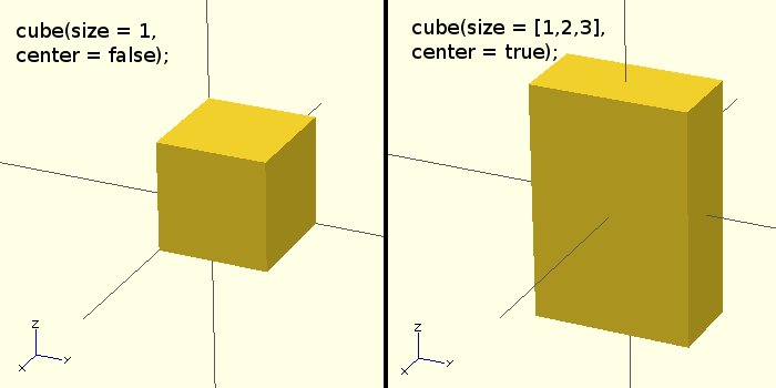
Creates a cube at the origin of the coordinate system. When centre is true the cube will exist centered on the origin, otherwise it is created in the outset octant. The argument names are optional if the arguments are given in the aforementioned club every bit specified in the parameters.
Parameters:
- size
- Decimal or iii value array. If a single number is given, the result will be a cube with sides of that length. If a three value array is given, and then the values will correspond to the lengths of the X, Y, and Z sides. Default value is 1.
- center
- Boolean. This determines the positioning of the object. If true, object is centered at (0,0,0). Otherwise, the cube is placed in the positive quadrant with one corner at (0,0,0). Defaults to false
Example 1:
cube ([2,three,4])
Example 2:
bottom_cube_length = two; bottom_cube_width = 3; bottom_cube_height = 2; cube ([bottom_cube_length, bottom_cube_width, bottom_cube_height], center=true) ;
Example 3:
cube(size = 1, center = false); cube(size = [1,2,3], center = true);
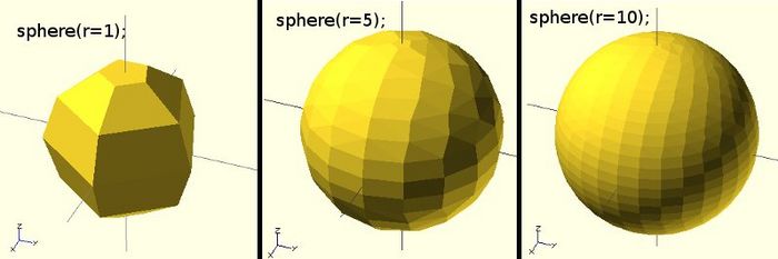
6.2 Sphere
Creates a sphere at the origin of the coordinate organization. The argument name is optional.
- Parameters
- r
- Decimal. This is the radius of the sphere. The resolution of the sphere will exist based on the size of the sphere and the $fa, $fs and $fn special variables.
Usage Examples
sphere(r = one); sphere(r = 5); sphere(r = 10); sphere(2, $fn=100); // high resolution sphere with a 2mm radius sphere(2, $fa=five, $fs=0.ane); // 2mm (less) loftier resolution sphere
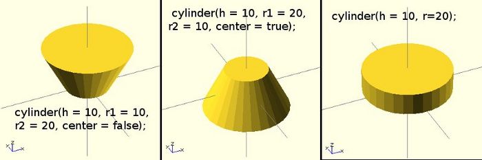
vi.iii Cylinder
Creates a cylinder at the origin of the coordinate system. When both radii are same information technology is also possible to specify a single radius using the argument name r. The argument names are optional if the arguments are given in the aforementioned guild as specified higher up.
Parameters
- h
- Decimal. This is the superlative of the cylinder. Default value is 1.
- r1
- Decimal. This is the radius of the cylinder/cone on height cease. Default value is one.
- r2
- Decimal. This is the radius of the cylinder/cone on bottom end. Default value is 1.
- r
- Decimal. The radius of both acme and bottom ends of the cylinder. Use this parameter if you desire a non-cone shaped cylinder. Default value is 1.
Usage Examples
cylinder(h = 10, r1 = x, r2 = 20, centre = false); cylinder(h = 10, r1 = 20, r2 = 10, center = true); cylinder(h = x, r=20);
6.four Polyhedrons
Polyhedrons are the most hard shapes to deal with. Instead of using this function, you could (a) think nigh how you could combine elementary forms instead or (b) look at second extrusion.
- A polyhedron (plural polyhedra or polyhedrons) is often defined equally a geometric solid with flat faces and straight edges.(Wikipedia, retrieved 17:25, 23 March 2010 (UTC)).
Any polyhedron tin can be built upwardly from different kinds of element or entity, each associated with a different number of dimensions:
- 3 dimensions: The body is bounded by the faces, and is usually the volume enclosed by them.
- two dimensions: A face is a polygon bounded by a excursion of edges, and usually including the flat (plane) region within the boundary. These polygonal faces together make upward the polyhedral surface.
- one dimension: An edge joins one vertex to some other and one face to another, and is usually a line segment. The edges together brand up the polyhedral skeleton.
- 0 dimensions: A vertex (plural vertices) is a corner point.
(Wikipedia, retrieved 17:25, 23 March 2010 (UTC)).
Syntax:
polyhedron(points = [ [x, y, z], ... ], triangles = [ [p1, p2, p3..], ... ], convexity = Due north);
Create a polyhedron with the specified points and triangles. (The 'pN' components of the triangles vector are 0-indexed references to the elements of the points vector.)
Example (meet picture below)
polyhedron ( points = [[0, -10, 60], [0, 10, threescore], [0, 10, 0], [0, -10, 0], [60, -10, lx], [threescore, 10, 60]], triangles = [[0,3,two], [0,2,1], [3,0,four], [i,2,5], [0,5,4], [0,1,5], [v,ii,4], [4,2,3], ]);

A uncomplicated hand-crafted Polyhedron
Note that OpenSCAD currently crashes if your polygons are non all oriented the same way; pay attention to the vertex ordering (don't understand this !) east.g.
polyhedron(points=[[0,0,0],[100,0,0],[0,100,0],[0,100,100]], triangles=[[0,1,ii],[0,ane,3],[0,2,3],[one,2,3]]); //Crashes polyhedron(points=[[0,0,0],[100,0,0],[0,100,0],[0,100,100]], triangles=[[0,1,2],[one,0,three],[0,2,iii],[2,i,3]]); //Works
An other example:

A hand-crafted Polyhedron
Let'south at present see how to set up polyhedrons with badly oriented polygons. When y'all select 'Thrown together' from the view menu and compile the blueprint (not compile and render!) you will see a preview with the mis-oriented polygons highlighted. Unfortunately this highlighting is non possible in the OpenCSG preview mode because it would interfere with the way the OpenCSG preview style is implemented.)
Below yous tin see such a problematic polyhedron, bad triangles are in pinkish.
// Bad polyhedron polyhedron ( points = [ [ 0 , - 10 , 60 ], [ 0 , 10 , threescore ], [ 0 , 10 , 0 ], [ 0 , - x , 0 ], [ 60 , - 10 , threescore ], [ 60 , 10 , sixty ], [ 10 , - 10 , 50 ], [ 10 , x , 50 ], [ ten , ten , 30 ], [ x , - 10 , 30 ], [ 30 , - x , 50 ], [ 30 , x , 50 ] ], triangles = [ [ 0 , ii , 3 ], [ 0 , 1 , 2 ], [ 0 , 4 , 5 ], [ 0 , 5 , i ], [ 5 , four , ii ], [ 2 , 4 , 3 ], [ 6 , 8 , nine ], [ 6 , 7 , 8 ], [ half-dozen , x , xi ], [ six , xi , 7 ], [ 10 , eight , eleven ], [ 10 , 9 , viii ], [ 0 , iii , nine ], [ 9 , 0 , 6 ], [ 10 , 6 , 0 ], [ 0 , 4 , 10 ], [ three , 9 , 10 ], [ 3 , 10 , iv ], [ 1 , seven , 11 ], [ 1 , 11 , 5 ], [ 1 , seven , 8 ], [ ane , eight , 2 ], [ ii , 8 , 11 ], [ 2 , eleven , 5 ] ] ); 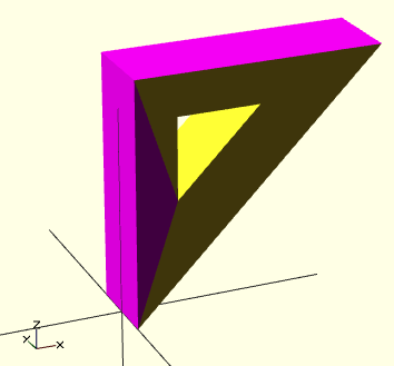
Polyhedron with badly oriented polygons
A right polyhedron would be the following:
polyhedron ( points = [ [ 0 , - 10 , sixty ], [ 0 , 10 , 60 ], [ 0 , 10 , 0 ], [ 0 , - 10 , 0 ], [ 60 , - ten , threescore ], [ lx , 10 , 60 ], [ ten , - 10 , 50 ], [ 10 , 10 , 50 ], [ ten , 10 , thirty ], [ 10 , - 10 , 30 ], [ 30 , - 10 , l ], [ 30 , 10 , 50 ] ], triangles = [ [ 0 , 3 , 2 ], [ 0 , ii , ane ], [ 4 , 0 , 5 ], [ 5 , 0 , 1 ], [ 5 , 2 , 4 ], [ four , 2 , iii ], [ half-dozen , eight , 9 ], [ half-dozen , 7 , 8 ], [ vi , 10 , 11 ],[ six , 11 , seven ], [ 10 , 8 , 11 ], [ x , nine , eight ], [ three , 0 , 9 ], [ 9 , 0 , 6 ], [ x , 6 , 0 ],[ 0 , four , 10 ], [ 3 , nine , 10 ], [ 3 , 10 , 4 ], [ one , seven , eleven ], [ ane , 11 , 5 ], [ 1 , 8 , 7 ], [ two , 8 , 1 ], [ eight , 2 , 11 ], [ v , 11 , 2 ] ] ); Beginner'south tip: If y'all don't really understand "orientation", and then just place the mis-oriented pink triangles and then permute the corresponding triangle's order of vertices until you become it right. E.1000. in the above example, the 3rd triangle vector (i.e. number 2, [0,four,5]) was incorrect and we fixed information technology as [4,0,5]. In addition you lot may select "Prove Edges" from the "View Card", make a screen capture, print it and number both the vertices (points) and the triangles. In our instance, the points are in blackness and the triangles in blueish. Then, plow the picture around and make a 2nd copy from the back if needed.

Polyhedron with badly oriented polygons
seven Transformations
7.1 scale
Scales its child elements using the specified vector. The argument proper name v is optional.
- Syntax
- scale(5 = [x, y, z]) { ... }
- Case
- Create an oval of length = 40 in the 10 direction; x and z remain the same.
scale ( 5 = [ 2 , 1 , i ]) cylinder ( h = ten , r = 20 ); 7.two rotate
Rotate accepts several versions of arguments.
- Syntax for second rotation around the Z-axis
-
rotate (deg)
Example:
- rotate(45) square(ten);
- Syntax for rotations about 1 or more than axis
- rotate(a = deg, v = [x, y, z]) { ... }
Rotates its child a degrees around the specified vector v rooted in the origin of the coordinate organisation.
Parameters:
- a
- Degrees
- v
- An array of [ten,y,z]
Case: rotates the object produced past module 8bit_char by 270 degrees around the z asis.
rotate ( a = 270 , five = [ 0 , 0 , i ]) { 8 bit_char ( char , size_mm , tiptop ); } - Alternative syntax
- rotate(a = [deg_x,deg_y,deg_z] { ... }
Parameters:
- a
- Vector of 3 degrees. In this case the kid nodes are rotated effectually the positive x, y and z axis (in this guild) by the specified number of degrees.
For example, to flip an object upside-down, yous might exercise this:
rotate(a=[0,180,0]) { ... } Notice: Argument names are optional if the arguments are given in the same order as specified to a higher place.
vii.iii translate
- Syntax
- interpret(v = [10, y, z]) { ... }
Translates (moves) its kid elements along the specified vector. The argument name is optional, i.e. the post-obit also works:
- interpret([x, y, z]) { ... }
seven.4 mirror
Mirror operation ([1,0,0] of a Lego Brick (original to the correct)
- Syntax
- mirror([ 1, 0, 0 ]) { ... }
Mirrors the child element on a plane through the origin. The argument to mirror() is the normal vector on that aeroplane.
translate ([- 100 , 0 , 0 ]) import ( "motivation.stl" ); color ( "red" ) { mirror ([ 1 , 0 , 0 ]) { interpret ([- 100 , 0 , 0 ]) import ( "motivation.stl" ); } }; 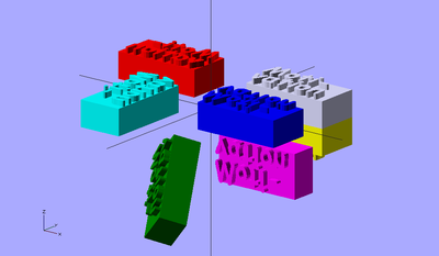
Mirror operations of a Lego Brick (original = grey to the right)
Imagine a orthogonal plane to the X axis that goes through the origin. This will exist the mirror.
translate ([- 100 , 0 , 0 ]) import ( "motivation.stl" ); color ( "red" ) { mirror ([ 1 , 0 , 0 ]) { translate ([- 100 , 0 , 0 ]) import ( "motivation.stl" ); } }; color ( "blue" ) { mirror ([ 0 , 1 , 0 ]) { translate ([- 100 , 0 , 0 ]) import ( "motivation.stl" ); } }; colour ( "cyan" ) { mirror ([ 1 , 1 , 0 ]) { interpret ([- 100 , 0 , 0 ]) import ( "motivation.stl" ); } }; color ( "yellow" ) { mirror ([ 0 , 0 , 1 ]) { translate ([- 100 , 0 , 0 ]) import ( "motivation.stl" ); } }; color ( "magenta" ) { mirror ([ 0 , 1 , i ]) { translate ([- 100 , 0 , 0 ]) import ( "motivation.stl" ); } }; color ( "dark-green" ) { mirror ([ 1 , 1 , 1 ]) { translate ([- 100 , 0 , 0 ]) import ( "motivation.stl" ); } }; 7.5 multmatrix
- Syntax
- multmatrix(k = [...]) { ... }
Example (translates by [10, 20, 30]):
multmatrix ( yard = [ [ 1 , 0 , 0 , 10 ], [ 0 , ane , 0 , twenty ], [ 0 , 0 , 1 , 30 ], [ 0 , 0 , 0 , 1 ] ]) cylinder (); Multiplies the geometry of all child elements with the given 4x4 transformation matrix.
7.half-dozen color
Usage instance: color([r, one thousand, b, a]) { ... } Displays the child elements using the specified RGB colour + blastoff value. This is but used for the OpenCSG and Thrown Together display modes. The alpha value will default to 1.0 (opaque) if not specified.
NB! The r, g, b, a values are limited to floating point values in the range { 0.0 ... one.0 } rather than the more traditional integers { 0 ... 255 }. Nonetheless you lot can specify the values equally fractions, e.g. for R,Yard,B integers in {0 ... 255} yous can apply:
color([ R/255, G/255, B/255 ]) { ... } If yous need only simple colors, apply something like (all CSS2/X11 colors should exercise):
color("red") cube () ; See the CSS3 colour names tabular array
7.seven minkowski
Minkowski sums allow to add together every chemical element of A to every chemical element of B. Not easy to understand and y'all also may read minkowski sum at cgal.org.
From the OpenScad Manual:
$fn = 50 ; minkowski () { cube ([ 10 , 10 , 2 ]); // rounded corners cylinder ( r = 2 , h = 2 ); } 
Rounding corner edges with Minkowski sum
To get rounded edges all over, once could utilise a sphere.
If you set $fn=50, information technology volition take ages to compute
$fn = 20 ; minkowski () { cube ([ ten , ten , two ]); // rounded corners sphere ( ii ); } 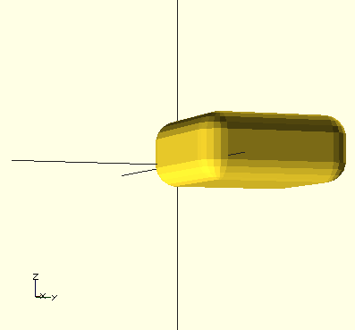
Rounding all edges with Minkowski sum
Inside a Minkowski clause, transformations do not seem to piece of work (May 2012).
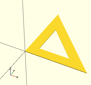
7.8 hull
hull volition create a hull from all objects that are within. Read convex hull at cgal.org if you lot desire to understand the principle.
$fn = xx ; hull () { # interpret ([ 0 , 0 , 0 ]) cylinder ( r = 2 , h = 2 ); interpret ([ ten , 0 , 0 ]) cylinder ( r = two , h = 2 ); translate ([ 5 , 10 , 0 ]) cylinder ( r = ii , h = 2 ); } 
Rounded triangle created with hull
8 CSG Modelling
viii.ane Principle
CSG stands for Effective solid geometry.
Information technology is possible to create complex 3D models past combining simple 3D archaic objects, such as cubes, cylinders or spheres.
8.2 Merging of objects
The result of union will be "broiled", i.e. if yous stack up cubes aligned against each other, the result will exist ane shape (no internal walls). This is ideal behavior for rapman printing. Note however, that juxtaposition of objects tin can go badly wrong, e.g. 2 cubes cannot share a single border as explained afterwards.
Example 1:
union () { interpret ( 0 , 0 , x ) import_stl ( "duck.stl" ); duplo ( ii , 2 , 1.5 , simulated ); } Example 2 (run into the picture below)
union () { cylinder ( h = 4 , r = ane , center = truthful , $fn = 100 ); rotate ([ 90 , 0 , 0 ]) cylinder ( h = four , r = 0.9 , center = true , $fn = 100 ); } 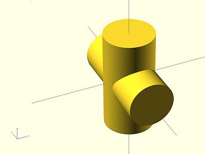
8.3 Difference
Difference substracts the 2nd (and all further) child nodes from the first 1.
Example 1:
divergence () { cylinder ( h = 4 , r = 1 , centre = true , $fn = 100 ); rotate ([ 90 , 0 , 0 ]) cylinder ( h = 4 , r = 0.9 , center = true , $fn = 100 ); } 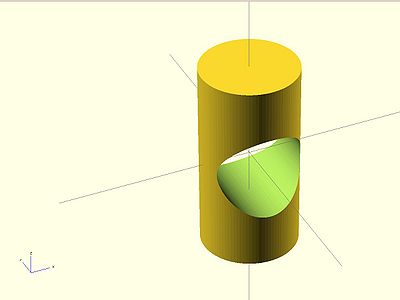
Example 2:
difference () { // starting time objects cylinder ( h = 4 , r = one , middle = truthful , $fn = 100 ); // first object that will substracted rotate ([ xc , 0 , 0 ]) cylinder ( h = iv , r = 0.9 , center = true , $fn = 100 ); // 2nd object that will be substracted rotate ([ 90 , 90 , 0 ]) cylinder ( h = 4 , r = 0.9 , center = true , $fn = 100 ); } You lot always should make sure that the extracting object is "longer" or "shorter" than the object from which you carve out. Else you lot can run into "object is non two-manifold issues" described in the troubleshooting section.
"Manifold" means that information technology is "water tight" and that there are no holes in the geometry. In a valid 2-manifold each border must connect exactly 2 facets. That means that the program must be able to connect a face with an object. Eastward.grand. if you utilize a cube of pinnacle ten to carve out something from a wider of cube of pinnacle ten, it is not clear to which cube the summit or the bottom belongs. And then make the small "extracting" cube a bit longer:
difference () { // original cube ( size = [ ii , 2 , two ]); // object that carves out # translate ([ 0.5 , 0.5 ,- 0.5 ]) { cube ( size = [ 1 , ane , 3 ]); } } 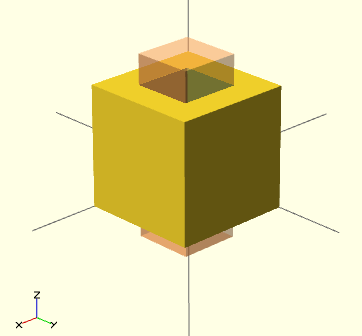
Right use of difference
viii.4 Intersection
Intersection creates the intersection of all child nodes. This keeps all the portions that overlap
Example:
intersection () { cylinder ( h = four , r = 1 , center = true , $fn = 100 ); rotate ([ 90 , 0 , 0 ]) cylinder ( h = iv , r = 0.9 , center = truthful , $fn = 100 ); } 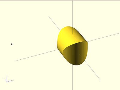
8.5 Modifier characters - assistance for composing
So-called modifier characters let you lot better run across what is going on. If you put one of these earlier a subtree you can meliorate understand what certain design elements practise (this is especially the instance for union, intersection and difference operations.
- # Debug modifier
- The subtree volition exist rendered, merely it besides volition be drawn in transparent pinkish
Example code:
divergence () { // kickoff objects cylinder ( h = 4 , r = 1 , center = true , $fn = 100 ); // showtime object that volition substracted # rotate ([ 90 , 0 , 0 ]) cylinder ( h = four , r = 0.three , center = true , $fn = 100 ); // 2nd object that will be substracted # rotate ([ 0 , 90 , 0 ]) cylinder ( h = iv , r = 0.nine , centre = true , $fn = 100 ); } 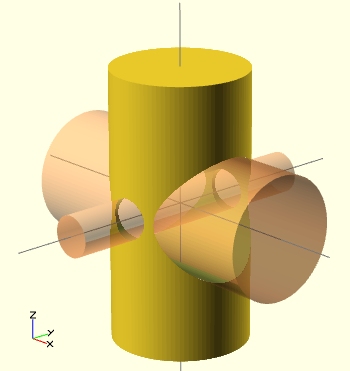
Debug Modifier instance
- % Background modifier
- Show a subtree in the background. Objects will be shown in low-cal gray and transformations applied, but the tree volition non be rendered.
Example:
difference () { // start objects cylinder ( h = 4 , r = 1 , center = true , $fn = 100 ); // first object that will substracted % rotate ([ 90 , 0 , 0 ]) cylinder ( h = 4 , r = 0.three , eye = true , $fn = 100 ); // second object that will be substracted % rotate ([ 0 , xc , 0 ]) cylinder ( h = 4 , r = 0.ix , center = truthful , $fn = 100 ); } 
Background modifier case
- ! Root modifier
Will ignore the residue of the design and employ this subtree every bit design root. Useful to have a look a unmarried chemical element, without having to copy/paste it to a smaller exam file.
Example: ! { ... }
- * Disable Modifier
Simply ignores this unabridged subtree. Same function equally commenting out with // Usage instance:
* { ... } 8.half-dozen Simple CSG examples
The following operation volition cut a Ball in half, flat side on bottom.
departure () { // A ball with a 5mm radius # sphere ( r = 5 , $fn = 100 ); // push 5mm downwards interpret ( v =[ 0 , 0 ,- v ]) { //The cube for cut # cube ( size = 10 , eye = true ); } } 
Solid dome
The following creates a unproblematic small basin.
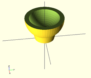
Simple 2cm x 2cm x 2cm+2mm bowl
// Resolution $ fn = 50 ; //Motion the pigsty thing upward interpret ( v = [ 0 , 0 , 12 ]) { difference () { difference () { // Outer Brawl sphere ( r = 10 , $ fn = 50 ); translate ( v = [ 0 , 0 , two ]) { //Inner Brawl sphere ( r = 8 , $ fn = 50 ); } } translate ( v = [ 0 , 0 , 5 ]) { // Cutting cube cube ( size = [ 20 , twenty , ten ], middle = true ); } } // Something to sit on interpret ( v = [ 0 , 0 , - ten ]) { cylinder ( h = 4 , r1 = five , r2 = 6 , center = true ); } } The post-obit creates a unproblematic keyholder
$fn = 20 ; difference () { hull () { # translate ([ 0 , 0 , 0 ]) cylinder ( r = 2 , h = 3 ); interpret ([ x , 0 , 0 ]) cylinder ( r = 2 , h = 3 ); translate ([ 5 , 40 , 0 ]) cylinder ( r = iv , h = 3 ); } translate ([ 5 , 38 ,- ane ]) cylinder ( r = 1 , h = v ); } 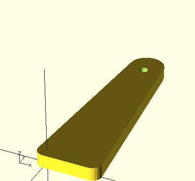
Keyholder made with hull (three Cylinders) and a Cylinder to punch a hole
See besides: Doblo factory, the just bigger project we attempted with OpenScad
9 second geometry and linear extrusion
Extruding 2d shapes into 3D shapes is - besides CSG modeling - the other way to create circuitous objects. There exist several possibilities and combinations:
- Type of extrusion: linear (including option torsion) and rotation (the 2d drawing is flipped 90 degrees and then extruded effectually the Z-axis
- Source: Built-in 2D graphis (circle, square, ellipse, regular polygones made from circles with $fn set, and polygons,
ix.1 Polygons
Polygones can have zero, one or several holes within.
Example without hole that could exist used to define the shape of some sofa walls:
color ( "red" ) linear_extrude ( tiptop = 19.2 ) polygon ( points = [[ 0 , 0 ],[ sixteen , 0 ], [ 16 , 32 ],[ 80 , 32 ],[ 80 , 0 ], [ 96 , 0 ], [ 96 , 48 ],[ 0 , 48 ] ]); 
Polygon case without pigsty (The motion picture includes a Doblo factory brick for reference
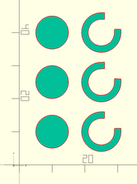
Instance code with i pigsty
polygon(points=[[0,0],[100,0],[0,100],[xv,xv],[65,xv],[15,65]], paths=[[0,ane,2],[3,4,5]]);
Polygon instance with one pigsty
In this case, we have exactly 6 points (three for the "outer" triangle, and three for the "inner" one). Then, we connect each with two two path. In plain English, each chemical element of a path must correspond to the position of a bespeak defined in the points vector, due east.grand. "1" refers to [100,0].
9.ii Linear 2d to 3D extrusion from builtin 2D shapes
From any 2D graphic we can extract 3D shapes. Let's look at polygones.
Case: Uncomplicated polygone
color ( "lightblue" ) linear_extrude ( height = xix.ii ) # polygon ( points = [[ 0 , 0 ],[ xvi , 0 ], [ sixteen , 32 ],[ lxxx , 32 ],[ 80 , 0 ], [ 96 , 0 ], [ 96 , 48 ],[ 0 , 48 ] ]); 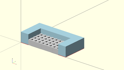
Extruded polygon example. The Lego in the motion-picture show was made with doblo factory and is but included for size reference
Example: Polygone with a hole
linear_extrude(height = 16, eye = truthful, convexity = 10, twist = 0) polygon(points=[[0,0],[100,0],[0,100],[15,15],[65,15],[15,65]], paths=[[0,ane,2],[iii,4,5]]);
Effect: A 16mm loftier flat triangle with an empty triangle inside

Extruded polygon example
Case: Extrusion from CSG created 2D shapes
Yous as well tin can create 2nd shapes with CSG. E.one thousand. you lot could create a kind of a moon shape past substracting a circle from a circle like this:
difference () { circle ( r = 10 ); translate ([ ii , 0 , 0 ]) circle ( r = 10 ); } A fuller example that includes some parameters is below:
module half_moon ( color = "orange" , size = 16 , thickness = four , fullness = 0.5 ) { color ( colour ) rotate ( a = [ 90 , 0 , 0 ]) linear_extrude ( superlative = thickness ) deviation () { circle ( r = size , $fs = 0.ii ); translate ([ size * 2 * fullness , 0 , 0 ]) { circle ( r = size , $fs = 0.2 ); } } } module moons () { half_moon ( size = 20 , fullness = 0.1 , color = "yellow" ); interpret ([ twenty , ten , 10 ]) half_moon ( size = 20 , fullness = 0.3 , color = "lightblue" ); translate ([ twoscore , 20 , 20 ]) half_moon ( size = ten , fullness = 0.5 , colour = "scarlet" ); } moons (); 
Extruded polygon from 2nd CSG moon
9.three Import and extrude 2D graphics from SVG
This section needs to exist updated. It is not longer necessary to flatten Bezier curves and to export to DXF - Daniel 1000. Schneider (talk)
You can import 2 types of SVG objects
- Closed polygone fills
- Lines, but these will exist translated to shapes
That means for instance, that fonts have to exist transformed to paths
According to the manual, OpenSCAD handles only closed polygons, and then importing lines or open polygons is not possible. Instead open polygons are treated as shapes divers by their stroke-width. "Closed shapes ignore fill up and stroke-width, open path apply stroke width to generate the outline of the shape."
Closed shapes are e'er using the geometric specification regardless of fill up or stroke-with defined in the SVG file every bit the following picture copied from the manual shows:
-

SVG in Inkscape
-
Imported into OpenSCAD
Example:
calibration ([ d_scale , d_scale , ane ]) linear_extrude ( height = d_height , centre = truthful , convexity = 10 ) import ( file = "test.svg" ); See also:
- Lego-compatible icon kit
9.3.1 Legacy procedure - Transforming and SVG file to a usable DXF file with Inkscape
This explains how to practice it with an older OpenScad version (to be removed once we have washed an example)
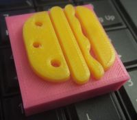
Lego-compatible Hamburger printed with 2 colors in PLA with a Felix Pro 1
Linear extrusion from imported graphics is a bit more catchy, since nosotros will have to start from a well made DXF file. Since available clipart is in SVG we will showtime from in that location, co-ordinate to the instructions past Nudel (thanks!).
Finding some clip art
Permit's create a 2D1/2 person, e.g. the kind 1 could find in certain platform games. At that place are two places with a good choice of SVG clipart.
- http:openclipart.org (all sorts of topics)
- https://thenounproject.com/ (huge icon collection)
With some search on Nounproject we found this women, a "public domain" icon.
- In order to download a file, y'all will have to register. For most icons, there is a public and a pay version. I you decide to use the public version, yous will have to give credits to the author. Nosotros practise this past inserting a comment in the scad file and hither.
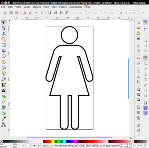
- Take the svg version. We renamed it to noun_woman.svg
This involves several steps. Basically, we have to transform the drawing into a a series of airtight connected "path definitions", where a path is composed of straight lines (and non curves).
(ane) Open the SVG in Inkscape and clean it
- Fit the certificate size to the picture size: Menu File->Document Properties.
- In the Custom size panel, open Resize page to content, then click Resize page to cartoon or pick
- Remove unused DEF'southward: File->Vacuum Defs.
- Optimize SVG: File -> Save equally... -> Optimized SVG.
- File -> Save as ... -> Apparently SVG
(2) Ungroup and remove the fill from the surfaces
- Ungroup everything (Hit SHIFT CTRL-G)
- Select all objects (CTRL-A)
- Add some stroke color if needed. Hit SHIFT CTRL-F
- Just in this case (fills are OK): Untick fill paint. Tick stroke paint (and select a color if necessary).
The result should look like this:
(iii) If necessary, move all layers to a single i. Kill the others.
(4) Translate all objects to paths
- Select the object(s) and spousal relationship iff the object is simple. Otherwise, I advise creating a carve up path for each part of the objects that should be filled
- Menu Path -> Union
- Select the remaining object and make information technology to path. You also could simplify it (before adding points again for creating a straight lines model)
- Menu Path->Object to Path. Now it's a unmarried path, consequence if it represents visually more one drawing. I suggest to do some node surgery after.
- Simplify if you lot tin
- Carte du jour Path->Simplify.
- Cheque if there are no other types of objects left
Open the XML editor (Card Edit->XML Editor). Brand sure that there are no other objects left.
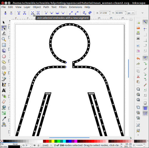
(five) Replace the splines (curves) by straight lines.
- Hit F2 (Edit path past nodes) to check if yous need more than nodes
- Select all nodes (east.g. click on some node, then press CTRL-A)
- Add more than nodes if necessary: Click Insert new nodes into selected segments (left most icon on acme).
- Click Brand segmented segments lines
Alternatively (and better in most cases):
- Select each path and transform Bezier curves to series of straight lines with an extension
- Utilise Extensions -> Modify Path -> Flatten Beziers before relieve as to Desktop Cutting Plotter (dxf).
- Enter a depression value, e.grand. 0.2 for a smaller icon
Repeat this process for other path in the drawing.
(6) Optional: Do some path surgery. If you lot need to bring together two path:
- Select two nodes from one path, Pause path at selected nodes
- Exercise the same with the other path
- Delete possibly some points (select and hit "DEL")
- Join 2 nodes (twice), using Join selected nodes
(half-dozen) Change the graphics (optional)
- e.g. nosotros made a nice skirt ...
- In case you make changes (e.one thousand. drag a node) make straight lines once again !
(half-dozen) Save every bit DXF
- File -> Save as; Select DXF
- Untick everything
Once you got a clean DXF you tin import the graphics and extrude
color ( "pink" ) linear_extrude ( pinnacle = v , center = true , convexity = x ) import ( file = "noun_woman-make clean.dxf" ); 
Getting a more complex drawing to import is more tedious, since one might desire to procedure each separate (not connected) subpath, as opposed to create a wedlock so translate all strokes.
- Cowgirl processed
-

Original cowgirl by Simon Child
-
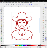
Simplified cowgirl (Simplified drawing, removed nodes, selected subpath, added nodes, transformed to directly lines (except some of the hair)
-
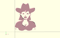
Simplified cowgirl imported and extruded
This object could be put on top of a Lego block or be substracted from one.
![]()
If nix shows
- Cheque if you lot really translated all segments to lines. Again, if you "union" your paths, then yous can do all in ane
- Check if there is Adobe lawmaking within the SVG. If there is, manually (with a text editor) get rid of it (after simplifying and optimizing and unionizing). A good instance is R2-D2 from Luis Pararas. Only after radically removing everything except the path it would piece of work. I did non investigate why. Actually it just could exist the switch statement.
9.4 Creating 3D text
Since version 2015.03 (March 2015), OpenScad has a text module that can produce second text that and so tin can be extruded. It works "as is" on Windows. As of March 2015, I did non exam Linux (Ubuntu), since I'd have to install the new version manually.
The text office accepts several arguments among which are:
- size (the gauge font height)
- font, the font name internal to OpenScad. Yous can get the list under the "help" card.
- halign and valign
- spacing, for spacing out letters (probably a good idea when using a filament printer)
Simple instance to create a text:

Extruded 2D text using a Windows Wingdings font
3D text example:
content = "Text rocks" ; font = "Liberation Sans" ; translate ([ - 30 , 0 , 0 ]) { linear_extrude ( peak = three ) { text ( content , font = font , size = 10 ); } } The example below says that spiders like their internet and uses Windows Wingdings. Unfortunately it probably is non easily portable. Windows fonts tin can be installed, but it's work.
content = "!Y\"" ; font = "Webdings" ; linear_extrude ( height = iii ) { text ( content , font = font , spacing = one.2 , size = 10 ); } From Giles BathGate, (retrieved dec 28 2010)
projection(cut=false) import_stl("/total/path/to/stl"); or
projection(cut=true) interpret([0,0,-ten]) rotate([0,90,0]) import_stl("file.stl"); So, "consign as" DXF: From the Pattern pull downwardly menu choose Consign as DXF.
ten Troubleshooting
10.1 Tracing
- Echo Statements
This function echoes the contents to the compilation window. Useful for debugging code
Usage examples:
my_h=50; my_r=100; echo("This is a cylinder with h=", my_h, " and r=", my_r); cylinder(h=my_h, r=my_r); 10.2 Non unproblematic objects
After compile and render GGAL (F6), yous may see something like:
Parsing design (AST generation)... Compiling design (CSG Tree generation)... Compilation finished. Rendering Polygon Mesh using CGAL... Number of vertices currently in CGAL cache: 600 Number of objects currently in CGAL cache: 3 Meridian level object is a 3D object: Simple: '''no''' Valid: yes Vertices: 200 Then when you try to export to .STL you go a message like:
Object isn't a valid 2-manifold! Change your design.. In a valid ii-manifold each border must connect extactly 2 facets. Here is a little case taken from the OpenSCAD Forum (retrieved 18:47, 22 March 2010 (UTC)):
module example1 () { cube ([ 20 , 20 , 20 ]); interpret ([- 20 , - 20 , 0 ]) cube ([ 20 , 20 , 20 ]); cube ([ fifty , 50 , 5 ], center = true ); } This example1 module is not a valid 2-manifold because both cubes are sharing one border. They bear upon each other but do non intersect.

A non valid 2-manifold cube (simple = no)
The example2 module below would ascertain a valid 2-manifold because there is an intersection (i.e. the cubes overlap a tiny flake). Now, each edge connects exactly ii facets and the two-manifold constraint is met.
module example2 () { cube ([ 20.i , 20.1 , 20 ]); translate ([- 20 , - 20 , 0 ]) cube ([ 20.1 , 20.one , 20 ]); cube ([ l , 50 , 5 ], middle = true ); } So, when performing composite solid geometry operations, information technology is important to remember that the slice you are subtracting must extend past the original office. (OpenSCAD Tip: Manifold Space and Fourth dimension, retrieved 18:47, 22 March 2010 (UTC)).
11 Thingiverse Customizer
Allows to create OpenScad files that volition allow users to parametrize. Yous will have to respect a few rules that are explained in the documentation.
Example lawmaking fragment:
/* [Running/Walking] */ RunningDistance = two ; //[two:100] RunningDuration = v ; //[x:600] /* [Dimensions] */ CutAway = 0.5 ; //[0.5,0.7,0.eight,1,1.five,2,3,iv]] HoleDiameter = iii ; //[one:5] ScaleFactor = i ; //[0.5,ane,one.v,2,2.5,3] /* [Subconscious] */ $ fn = 100 ; //sets the smoothness of the whole 12 Links
- http://openscad.org/
- http://en.wikibooks.org/wiki/OpenSCAD_User_Manual
12.ane Tutorials
- Open Scad tutorial serial at Makerbot (several good blog articles)
- Forepart page of OpenScad has some good tips on effective solid geometry (aka CSG)
- posts with label OpenSCAD on I Love Robotics]. The OpenSCAD Tip: Linear and Rotational Extrusions is a must read for beginners.
- Hack a Day: How To: Make a Printable CES Badge
- Make: Projects - Simple 3D models with OpenSCAD. Explains how to create a "2D" 12 solid pentomino puzzle
- OpenSCAD Tip: Manifold Space and Time Read if y'all desire to create water tight models.
- Other stuff
- Mashups (discussion on the BFB education forum)
- Parametric Duplo (modern by DKS on Thingyverse)
12.ii In teaching
- 3D Printed Science Projects, Ideas for your classroom, science off-white or home. By Joan Horvath , Rich Cameron. Cheap east-book/print volume from APress. Includes downloadable code.
12.3 Thingiverse Customizer
- Documentation
- All-time Practices
- Preview (you tin copy paste lawmaking to test the interface).
- beads example
12.4 Geometric forms / 3D models
- 3D modeling (Wikipedia)
- Polygon Mesh (Wikipedia)
- Vertex (Geometry), Wikipedia
- Edge (geometry) (Wikipedia)
- Face (geometry) (Wikipedia).
- polyhedronl (Polyhedron)
12.5 Software
- OpenScad
- http://www.openscad.org/ (OpenScad download, either source or Win / Mac / Linux binaries)
- Utilities
- Inkscape to OpenSCAD converter v2. Inkscape extension to export Inkscape paths to OpenSCAD. This extension handles SVG arcs, clones, circles, ellipses, groups, lines, paths, polygons, polylines, rects, and splines. It as well follows certificate transforms equally well as viewports. Either an entire document or but the selected portions of a document are processed.
- svgto3d Get a list of svg files and convert them to prepared scad designs. Y'all'll so have to change just the size. This is a read-to-become bash script for Linux/Unix. (to go this work on Win/Mac etc., installation piece of work may be required ....). Nether Debian/Ubuntu, you may need to: sudo apt-get install pstoedit
12.6 Alternatives to OpenSCAD
- https://emacstragic.net/programmatic-cad-openscad-alternatives/
thirteen Credits and copyright modification
- Parts of this article were taken from OpenSCAD User Manual
- Note: Past default, pictures were originally mine. Meantime to writing this slice, I fabricated updates to the transmission on Wikibooks. Else, pictures are taken from the OpenSCAD Manual and the legends should say then...
roywitheyesse1999.blogspot.com
Source: https://edutechwiki.unige.ch/en/OpenScad_beginners_tutorial
0 Response to "A Cube Is an Example of a? Art 1"
Post a Comment